
To connect to a PPE/PPC platform vehicle simulation in ODIS Service, the DoIP protocol must be used. CAN communication is not available for this platform, and the system enforces a switch to DoIP mode. This is likely related to the fact that vehicles on the PPE or PPC platform are not always diagnosed stably over the CAN bus for some reason.
Starting from version 2.4, VCTool ECU Simulator Ultimate supports DoIP in addition to CAN. CAN remains required because the initial VIN read request is performed over CAN. Once the diagnostic session begins, ODIS-S automatically switches the VCI to DoIP mode, and all further communication is carried out over DoIP.
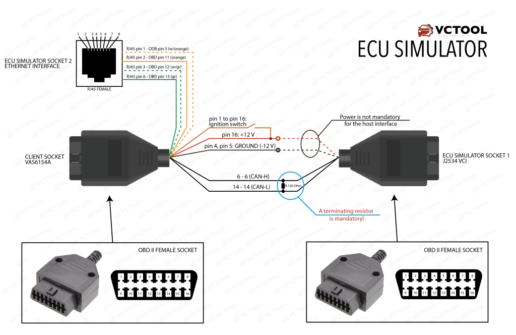
To set up the simulation, a small test bench must be assembled. The required components are:
- Two OBD2 female connectors
- One RJ45 female connector
- A 12 V power connector
- A switch to simulate ignition
- A 120 Ω resistor for CAN bus termination
- A USB-to-Ethernet adapter for DoIP operation (if the PC has no available Ethernet port)
- A UTP patch cable to connect the bench to the network interface
- An original VAS6154A for use with ODIS-S
- A J2534 interface to serve as the host interface for ECU Simulator over CAN
Attention! An original VAS6154A is required. Chinese clones (such as VNCI6154 or grey fake VAS6154 units with serial numbers starting with 7) do not function properly over Ethernet—the interface freezes until the Ethernet module is fully reset. The issue appears to be related to firmware or hardware design. At present, the manufacturer has not provided any official clarification.
The bench wiring diagram is shown below.
After loading the simulator or a backup, select the Ethernet interface to be used for DoIP in the settings. When the simulator starts, the DoIP module is enabled automatically if a network link is detected and disabled if the link is lost.
When DoIP is active, the status bar displays a green “CAN+DoIP” indicator. In this mode, the simulator responds simultaneously over CAN and DoIP.